How To Measure The Output Impedance Of Your Guitar

What Is The Output Impedance And Why Do I Even Care About It?

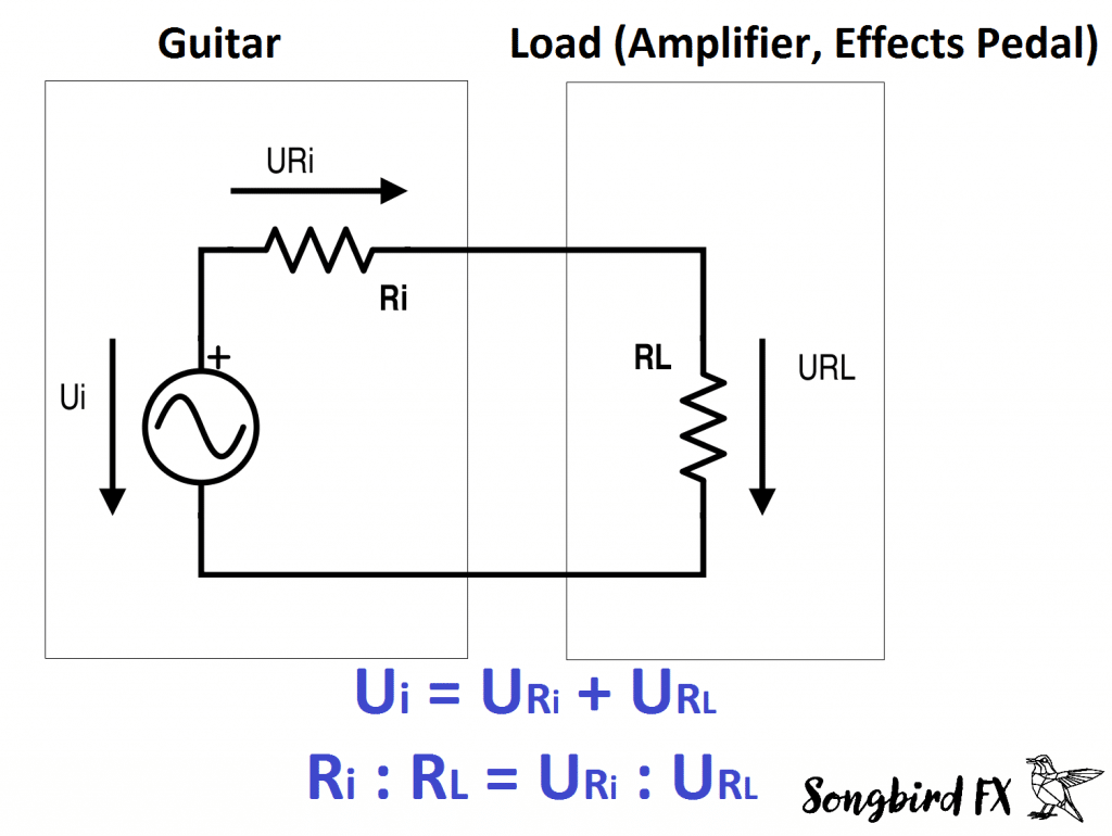
The output impedance or source impedance Ri of a perfect signal source is 0Ω. When talking about DC voltage sources it is also called internal resistance (That’s why I call it Reven though a guitar pickup is an AC signal source). A (passive) guitar pickup is by no means a perfect signal source (Ri > 0). This means that the output voltage will drop when connected to a load (effects pedals, amplifier). This effect will be more significant the higher the output impedance of your guitar pickup and the lower the input impedance of your amplifier/effects pedal is (voltage divider between Ri and RL).

guitar output impedance thevenin internal resistance effects pedal buffer voltage divider
voltage divider between output impedance Ri of the guitar and input impedance RL of the load

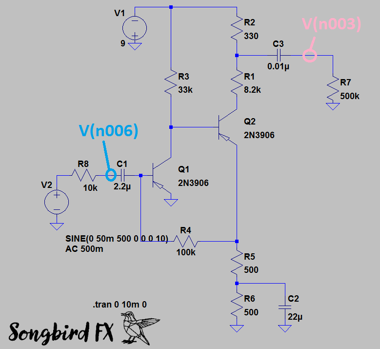
Recently I simulated the circuit of a Fuzz Face with LTspiceIV and realized that the output impedance of the guitar affects the final output waveform of the effects pedal.

Example:

Fuzz Face Schematic:

Fuzz Face Simulation Sound LTspice circuit impedance

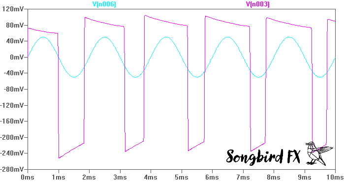
Output Waveform Of A Fuzz Face With Perfect Signal Source (Ri=0Ω) At Input:

Fuzz Face Simulation with Buffer Pedal perfect signal source


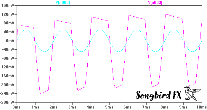
Output Waveform Of A Fuzz Face With Realistic Signal Source (Ri=10kΩ) At Input:

Fuzz Face Simulation LTspice Output Impedance Guitar

You have to find out for yourself if you like the sound of those interactions or not. If you don’t like it you should reconsider the order in which your guitar effects are arranged in your signal chain. Buffer and booster/preamp pedals have a high input and a low output impedance. They can be used to preserve the original waveform coming from your guitar pickups when used as the first pedal in your signal chain. Active guitar pickups are even better than buffer pedals because the guitar cable is a (capacitive) load too.

How To Measure The Output Impedance Of Your Guitar Pickup?

For measuring the source impedance of your guitar you will need an oscilloscope. If you don’t have one you can use my results because it won’t differ that much. By the way the exact model name of my guitar pickup is a Seymour Duncan SH-4 JB in bridge position.

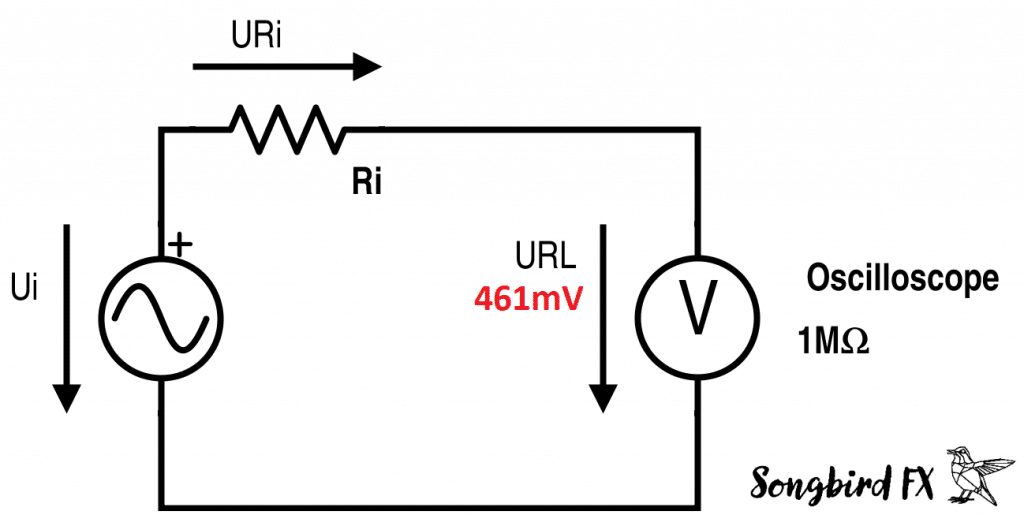
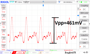
  1. Measure The Peak-Peak Voltage With Open Output:
    Turn your guitar up to full volume to make sure that the pots don’t influence your measurement. Then strum a note (I strummed the thicker E string).
    guitar source impedance measurement calculation output impedance

    peak peak voltage vpp guitar output e string signal waveform without load

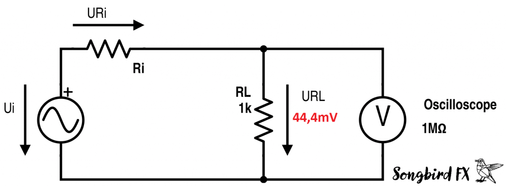
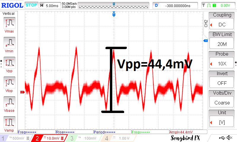
  2. Measure The Peak-Peak Voltage With A Load (RL=1k):
    Strum the same note with the same intensity as before to get the best results.
    guitar internal resistor calculation measurement impedanceoutput waveform of a guitar maximum typical output with load measurement

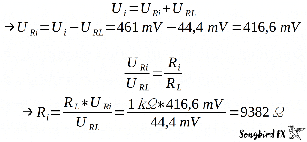
  3. Calculate The Output Impedance Of Your Guitar Pickup:
    Finally we can take the voltage divider formulas from above and substitute the variables with our measured values.
    calculation guitar output impedance voltage divider formula
    Result: The output impedance of my guitar is about 10kΩ.

Note: The impedance changes with frequency. This result is only true for the lower E-string, however we can assume that it won’t change dramatically. To get a more detailed result you can repeat this procedure at different frequencies (different notes).

USB Rechargeable Guitar Effects

Are you tired of low 9V batteries in your pedals? This is now over! My company Songbird FX invented the world’s first USB rechargeable Overdrive pedal, the Bluebird Drive. Below you find a video of the Germanium version, produced by the great Mike Hermans.


Interested? Click here for more information!

How Does The Tone/Volume Control Of A Guitar Work?

Gibson style guitars usually have two humbucking pickups, a tone and a volume potentiometer for each humbucker and a toggle switch to select the pickup. How exactly are these components wired together and how do the pot settings affect your sound? In this little article I will give you an answer to these questions and tell you some advantages and disadvantages of this wiring scheme. I will also show you the frequency response of the different settings.

Wiring Scheme

gibson style wiring scheme tone volume potentiometer pot capacitor cap toggle switch humbucker humbucking pickup les paul sg explorer es
Please note: the middle position of the toggle switch is not correctly drawn. Actually both pickups are connected to the output in the middle position.

In the diagram you can see that each pickup has independent tone and volume controls. The obvious advantage of this wiring scheme is that you can set two independent sounds and easily switch between them via the toggle switch.

Example Settings:
  • Classic Rock
    Neck pickup: Volume 100%, Tone 0% (creamy lead sound)
    Bridge pickup: Volume 70%, Tone 100% (crunchy rhythm sound)
    This is a typical classic rock guitar setting where you can switch between lead and rhythm sound.
  • Kill Switch
    Neck pickup: Volume 0%, Tone 100% (short circuit – no output)
    Bridge pickup: Volume 100%, Tone 100% (high output lead or rhythm sound)
    This setting can be used as a special effect instead of a kill switch: Quickly move the toggle switch up and down to create a tremolo-like effect.

One disadvantage of independent volume control is that the mix position of the toggle switch is only useful, if you match the volume settings of both pickups. If you don‘t, one pickup outweighs the other and you can‘t hear much of a difference to the single pickup sound.

Another disadvantage of passive volume control in general is that at lower volume settings the output impedance is very high -> Your signal is more sensitive to electromagnetic disturbances and gets noisier. You don’t have this problem with active guitar pickups.

Frequency Response

I simulated the frequency response of different settings with LTspice XVII. The signal source I used has a flat frequency response and a 10k output resistance.

simulating guitar frequency response tone volume control gibson les paul

frequency response guitar gibson style tone volume setting pot potentiometer attenuation curve db
Frequency response: Different volume settings and different tone settings.
Conclusions:
  • The tone control is an adjustable lowpass filter
  • The tone setting does not change at different volume settings (the cut-off frequency stays the same)
  • Significant tone change only happens between 0%-10% of the tone pot value -> I recommend using audio taper potentiometers to compensate this unlinearity

I hope this article is useful to you. Please check out the products on this website: My company Songbird FX is a manufacturer of high-quality micro-USB rechargeable guitar pedals.

How To Choose An Op Amp For Your Audio Project

op amp circuit symbol basics audio project guitar pedal how to choose select
circuit symbol

Selecting the right operational amplifier (short: op amp) for your DIY-project can be a hard task. The variety of op amps is comparable to the number of stars in the sky and the number of specifications in the datasheet is sometimes overwhelming, so how do you choose the right op amp for a specific project? In the following I want to give you an overview of the most important datasheet specifications that you should look after. This little guide is addressed to electronics beginners who want to dive a bit deeper into the topic of operational amplifiers.

What Is An Operational Amplifier?

An operational amplifier is basically a differential amplifier with a very high amplification (ideally infinite). It has a non-inverting and an inverting input, an output and of course pins for the power supply. By using feedback from the output to one of the inputs you can realize many different circuits, for example inverting and non-inverting amplifiers (with finite amplification), integrators, differentiators, low-pass and high-pass filters and many more. For further reading on the different circuits check out Texas Instruments’ “AN-20 An Application Guide For Op Amps”.

The Most Important Datasheet Specifications:

1. Supply Voltage

The one most important spec you should check in the datasheet is the Supply Voltage Range. You find it at Recommended Operating Conditions. If your Supply Voltage is too low your op amp won’t work properly, if it is too high you may even destroy it.

2. Input Common Mode Voltage Range

This specification is sometimes overlooked. The Input Common Mode Voltage Range defines the allowed voltage range of your inputs without malfunction of the op amp. Op amps with rail to rail inputs have an Input Common Mode Voltage Range of V- < Vin < V+, others may include only the positive or the negative rail or neither.

Example:
The typical Input Common Mode Voltage Range of the TL072 includes the positive rail and needs 3 volts of margin to the negative rail:
V- + 3V < Vin < V+                             at 10V supply voltage your input voltage range is 3V to 9V

In the Recommended Operating Conditions TI adds a big safety margin:
V- + 4V < Vin < V+4V                    at 10V supply voltage your input voltage range is only 4V to 6V.

If you want to design your circuit properly you have to use the voltage range stated in the Recommended Operating Conditions (minimum values), however, if you are developing an individual item you can get by with using the typical values by screening the op amps.

3. Input Impedance

The Input Impedance of op amps is of special interest when the signal source impedance is high, for example when using passive guitar pickups. If so, you may want to choose an op amp with JFET-inputs (Input Impedance goes up to 1000GΩ). Op amps with bipolar inputs typically have Input Impedances of about 10MΩ.

4. Equivalent Input Noise and Typical Harmonic Distortion

Op amps do not only amplify your source signal, they also add harmonics and noise. The Equivalent Input Noise and Typical Harmonic Distortion are either stated separately or mixed together as THD+N.
For audio applications it is essential to choose an op amp with low noise and distortion.

5. Supply Current

If your device runs on batteries it is important to keep an eye on the Supply Current. The Supply Current or Quiescent Current provides information on the energy consumption of the op amp without load.
Unfortunately the rule applies that low supply currents result in high noise. You see, choosing the right component is always a trade-off – welcome to electronics 😉

6. Output Impedance

The Output Impedance is important if the load impedance is low, for example if you want to drive headphones or an LED. The Output Impedance has to be much lower than the load impedance, otherwise there would be a big voltage drop on the output (voltage divider between Output Impedance and load impedance). If you don’t find the Output Impedance in your datasheet the Output Source Current gives you similar information.

For detailed information on the above stated specifications and more I recommend you to read TI’s “Understanding Operational Amplifier Specifications“.

How Do I Find The Right Op Amp?

I personally like to use the website of Texas Instruments, because I can type in the specifications that are important to me and the website then shows me suitable op amps including an approximate price. If you want to include other manufacturers too, a great way to do this is using the search function of a big distributor, e.g. Mouser.

I hope this little guide is useful to you. If you are a guitar player, please check out the products on this website: My company Songbird FX is a manufacturer of high quality micro-USB rechargeable guitar pedals.